
- Community Home
- >
- Networking
- >
- Switching and Routing
- >
- Comware Based
- >
- Re: Help configuring IRF on four 5700 switches
Categories
Company
Local Language
Forums
Discussions
Forums
- Data Protection and Retention
- Entry Storage Systems
- Legacy
- Midrange and Enterprise Storage
- Storage Networking
- HPE Nimble Storage
Discussions
Discussions
Discussions
Forums
Discussions
Discussion Boards
Discussion Boards
Discussion Boards
Discussion Boards
- BladeSystem Infrastructure and Application Solutions
- Appliance Servers
- Alpha Servers
- BackOffice Products
- Internet Products
- HPE 9000 and HPE e3000 Servers
- Networking
- Netservers
- Secure OS Software for Linux
- Server Management (Insight Manager 7)
- Windows Server 2003
- Operating System - Tru64 Unix
- ProLiant Deployment and Provisioning
- Linux-Based Community / Regional
- Microsoft System Center Integration
Discussion Boards
Discussion Boards
Discussion Boards
Discussion Boards
Discussion Boards
Discussion Boards
Discussion Boards
Discussion Boards
Discussion Boards
Discussion Boards
Discussion Boards
Discussion Boards
Discussion Boards
Discussion Boards
Discussion Boards
Discussion Boards
Discussion Boards
Discussion Boards
Discussion Boards
Community
Resources
Forums
Blogs
- Subscribe to RSS Feed
- Mark Topic as New
- Mark Topic as Read
- Float this Topic for Current User
- Bookmark
- Subscribe
- Printer Friendly Page
- Mark as New
- Bookmark
- Subscribe
- Mute
- Subscribe to RSS Feed
- Permalink
- Report Inappropriate Content
01-21-2018 07:57 AM
01-21-2018 07:57 AM
Hello,
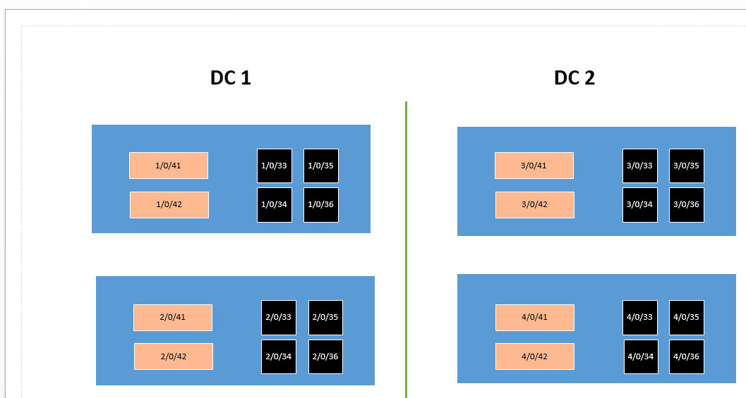
I wonder if someone can give me a suggestion on how to phicically link four 5700 FF switches on a IRF stack: I'm not a networking guy but would need to do it myself. So I have two 5700 switches located in Datacenter on top of each other 1 and two 5700 switcehs located in Datacenter 2 again on top of each other. The two Datacenters are about 0.3 miles apart. See diagram attached. The pink ports are the 40Gb links , the black ports are the 10 GB SFP+ ports. Between the two Datacenters unfortunately for now I only have one single Multimode 10GB SFP cable , the customer will put an additional one but not now. I have already changed the irf memeber numbers and prority on the relevant switches and all the SFP+ and 40 GB cables are disconnected
how do I link them together and what ports would I include in
irf-port group 1/1
irf-port group 1/2
irf-port group 2/1
irf-port group 2/2
irf-port group 3/1
irf-port group 3/2
irf-port group 4/1
irf-port group 4/2
Please see attached file
Thanks a lot
Fabio
Solved! Go to Solution.
- Mark as New
- Bookmark
- Subscribe
- Mute
- Subscribe to RSS Feed
- Permalink
- Report Inappropriate Content
01-21-2018 04:10 PM - edited 01-21-2018 04:18 PM
01-21-2018 04:10 PM - edited 01-21-2018 04:18 PM
Solutioncalleghf wrote: Hello,
I wonder if someone can give me a suggestion on how to phicically link four 5700 FF switches on a IRF stack: I'm not a networking guy but would need to do it myself. So I have two 5700 switches located in Datacenter on top of each other 1 and two 5700 switcehs located in Datacenter 2 again on top of each other. The two Datacenters are about 0.3 miles apart. See diagram attached. The pink ports are the 40Gb links , the black ports are the 10 GB SFP+ ports. Between the two Datacenters unfortunately for now I only have one single Multimode 10GB SFP cable , the customer will put an additional one but not now. I have already changed the irf memeber numbers and prority on the relevant switches and all the SFP+ and 40 GB cables are disconnected
how do I link them together and what ports would I include in
irf-port group 1/1
irf-port group 1/2
irf-port group 2/1
irf-port group 2/2
irf-port group 3/1
irf-port group 3/2
irf-port group 4/1
irf-port group 4/2
Please see attached file
Thanks a lot
Fabio
A lot can be suggested about IRF deployment...but you're actually pretty limited by the only one FO physical link between your two DCs...this only one physical link actually means that you (a) can only deploy an IRF Chain Topology involving all four Switches and, within this choice, (b) IRF Ports' bound interface used to connect the node on DC1 to its neighbour node on DC2 will be limited to one 10G (SFP+) or 40G (QSFP+) Interface (so no enhanced resiliency and throughput on IRF Ports which are DC facing, IRF Member 2 and 3 in case of a Chain or IRF Member 2, 3 and 4, 1 in case of a Ring).
Restriction (b) above doesn't necessarily mean that you can't adopt such IRF Port binding strategy between IRF members whitin each DC...but this will lead to an asymmetry (which is totally permitted if you have physical restrictions as you stated): best practice examples tend to show that IRF Members are always connected using the same IRF Port binding strategy (single link, multiple links and same type of ports, either 1G - where permitted - 10G, 40G or 100G) and this means generally a sort of symmetry/balancing with regard to IRF Ports (independently by Chain/Ring topologies).
Restriction (a) should fall if you can add a second FO link between your DCs and so you can deploy IRF Ring topology.
Possible approaches could be:
- To use 40G QSFP+ Interfaces: deploy IRF Chain topology then, once the second FO physical link will be available, use this one to form the loop between 4th IRF Member (on DC2) and 1st IRF Member (DC1) IRF Ports...transforming the initial IRF Chain topoloy into a IRF Ring topology; this approach supposes that you can start with a DC1-DC2 interconnection involving 40G Interfaces using the existing FO link and then add another equal one FO deployed with 40G Transceivers in a near/far future.
- To use only 10G SFP+ Interfaces: deploy IRF Chain topology, each IRF Port within each DC will be bound to two 10G Interfaces (so IRF Ports within each DC will gain throughput and resiliency being aggregated), both IRF Ports of IRF Members neighbouring DCs will instead use initially only one 10G physical interface bound to each respective IRF Port (that's the asymmetry)...once the second FO link will be available, add this new 10G Interface to respective IRF Ports (2nd and 3rd IRF Members) rebalancing the asymmetry into symmetrical IRF links (all 10G+10G on each IRF Member involved); this approach supposes that you can start with a DC1-DC2 interconnection through 10G Interfaces using the existing FO link and then add another equal one in a near/far future.
- [it should be possible - to be verified - I don't believe there is a restriction about IRF Port 1 and Port 2 on each Switch requiring that both IRF Ports - 1 and 2 - must concurrently be bound to the same type and number of physical interfaces <- a restriction there is when you connect IRF Ports of neighbouring IRF Members, those IRF Ports need to be necessarily bound to similar physical interfaces] Use the approach outlined above on (2) but use IRF Ports bound to 40G Interfaces on IRF Members of each DC if you want (so between IRF Member 1 IRF Port 1 and IRF Member 2 IRF Port 2 and between IRF Member 3 IRF Port 1 and IRF Member 4 IRF Port 2) depolying only one 10G Interface bound to each IRF Port of IRF Members which are DC facing - 2nd and 3rd Member - because you have only one FO link available supposedly at 10G (so between IRF Member 2 IRF Port 1 and IRF Member 3 IRF Port 2), here the asymmetry is between DCs - throughput within them will be unbalanced - in comparison to what happen within each DC (10G link East-West between DCs where you have 40G links North-South within DC).
I'm not an HPE Employee

- Mark as New
- Bookmark
- Subscribe
- Mute
- Subscribe to RSS Feed
- Permalink
- Report Inappropriate Content
01-21-2018 11:52 PM
01-21-2018 11:52 PM
Re: Help configuring IRF on four 5700 switches
Hello Parnassus,
Thanks a lot for your time are really detailed explanation. It's really a great help for me and help to clarify many things,
Thanks again
Fabio
- Mark as New
- Bookmark
- Subscribe
- Mute
- Subscribe to RSS Feed
- Permalink
- Report Inappropriate Content
01-23-2018 01:56 PM
01-23-2018 01:56 PM
Re: Help configuring IRF on four 5700 switches
Hello Fabio,
I forgot to add at least another two possible approaches...both don't involve a full four IRF Members domain as solutions already discussed, both approaches instead involves two IRF Members per IRF Domain...that's actually something you didn't looking for but, maybe, something that is worth to consider too...especially if you have the single DC1-DC2 link restriction.
- Two separated IRF Domains (Domain 1 on DC1 and Domain 2 on DC2): each IRF Domain will be setup using two IRF Members within the same considered DC then deploy a full mesh of Port Trunking uplinks (basically any to any) between separated IRF Domains (so IRF Member 1 of IRF Domain 1 will be uplinked concurrently to IRF Members 1 and 2 of IRF Domain 2, IRF Member 2 of IRF Domain 1 will uplinked concurrently to IRF Members 1 and 2 of IRF Domain 2...that's a full mesh of uplinks between DC1 and DC2)...in your case you are lacking three of four required physical links between DCs...so it could be an interesting scenario to be deployed once you will be able to arrange three additionals physical links in addition to the one you already have.
- Two separated IRF Domains (Domain 1 on DC1 and Domain 2 on DC2): each IRF Domain will be setup using two IRF Members within the same considered DC then use just a single uplink between IRF Domains (free choice of peering interfaces and peering IRF Members on both sides, no redundancy)...that is just a way to interconnect two virtual switches (IRF Domain 1 on DC1 to IRF Domain 2 on DC2) using the single physical link you already have...eventually setting up that physical link as the only one member of a Port Trunking Interface (LACP Dynamic) to which - in future - add/bind the additional planned 10G link.
Just to complete the picture...
I'm not an HPE Employee