
- Community Home
- >
- Networking
- >
- Wireless
- >
- M and MSM Series
- >
- Re: Implementation WIFI network using MSM 760
Categories
Company
Local Language
Forums
Discussions
Forums
- Data Protection and Retention
- Entry Storage Systems
- Legacy
- Midrange and Enterprise Storage
- Storage Networking
- HPE Nimble Storage
Discussions
Discussions
Discussions
Forums
Discussions
Discussion Boards
Discussion Boards
Discussion Boards
Discussion Boards
- BladeSystem Infrastructure and Application Solutions
- Appliance Servers
- Alpha Servers
- BackOffice Products
- Internet Products
- HPE 9000 and HPE e3000 Servers
- Networking
- Netservers
- Secure OS Software for Linux
- Server Management (Insight Manager 7)
- Windows Server 2003
- Operating System - Tru64 Unix
- ProLiant Deployment and Provisioning
- Linux-Based Community / Regional
- Microsoft System Center Integration
Discussion Boards
Discussion Boards
Discussion Boards
Discussion Boards
Discussion Boards
Discussion Boards
Discussion Boards
Discussion Boards
Discussion Boards
Discussion Boards
Discussion Boards
Discussion Boards
Discussion Boards
Discussion Boards
Discussion Boards
Discussion Boards
Discussion Boards
Discussion Boards
Discussion Boards
Community
Resources
Forums
Blogs
- Subscribe to RSS Feed
- Mark Topic as New
- Mark Topic as Read
- Float this Topic for Current User
- Bookmark
- Subscribe
- Printer Friendly Page
- Mark as New
- Bookmark
- Subscribe
- Mute
- Subscribe to RSS Feed
- Permalink
- Report Inappropriate Content
12-21-2015 08:44 AM
12-21-2015 08:44 AM
Implementation WIFI network using MSM 760
Hello Forum,
I am trying to implement WIFI network here and runing into problem.
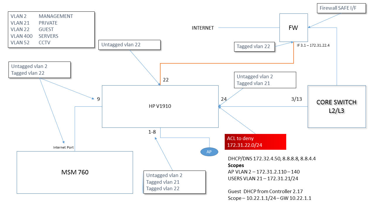
Below is the architecture.
The problems:
1) guest users traffic isn't going to FW interface - instead routing back to the core switch.
2) few minutes ago - I rebooted the controller and now AP are no longer visable to the controller. now getting this:
any help much appreciated.

v1910 config is
#
version 5.20, Release 1513P99
#
sysname har-wfi-sw-01
#
clock timezone UTC add 00:00:00
#
super password level 3 cipher $c$3$S5qJ++iUrcWItWPoqyCASKz8otlwpoyzozs=
#
dhcp relay server-group 0 ip 172.31.4.50
#
domain default enable system
#
ip ttl-expires enable
#
lldp enable
lldp compliance cdp
#
password-recovery enable
#
acl number 3001 name DENY-GUEST
rule 0 deny ip source 192.168.0.0 0.0.255.255 destination 172.31.70.0 0.0.1.255
rule 5 permit ip
#
vlan 1
description DEFAULT
#
vlan 2
description VLAN 2
#
vlan 21
description VLAN 21
#
vlan 22
description VLAN 22
#
vlan 52
description VLAN 52
#
radius scheme system
#
domain system
access-limit disable
state active
idle-cut disable
self-service-url disable
#
user-group system
#
local-user admin
password cipher $c$3$QV1TDjaIyCnLjir+42HRCYFqwVtHbD42eZhTDH5lwsY=
authorization-attribute level 3
service-type ssh telnet terminal
service-type web
#
stp mode rstp
stp enable
#
interface NULL0
#
interface Vlan-interface1
ip address 192.168.2.2 255.255.255.0
dhcp relay server-select 0
#
interface Vlan-interface2
ip address 172.31.2.18 255.255.255.0
dhcp select relay
dhcp relay server-select 0
#
interface Vlan-interface21
ip address 172.31.21.3 255.255.255.0
dhcp select relay
dhcp relay server-select 0
#
interface Vlan-interface22
ip address 172.31.22.3 255.255.255.0
#
interface GigabitEthernet1/0/1
port link-type hybrid
undo port hybrid vlan 1
port hybrid vlan 21 to 22 tagged
port hybrid vlan 2 untagged
port hybrid pvid vlan 2
poe enable
stp edged-port enable
#
interface GigabitEthernet1/0/2
port link-type hybrid
undo port hybrid vlan 1
port hybrid vlan 21 to 22 tagged
port hybrid vlan 2 untagged
port hybrid pvid vlan 2
poe enable
stp edged-port enable
#
interface GigabitEthernet1/0/3
port link-type hybrid
undo port hybrid vlan 1
port hybrid vlan 21 to 22 tagged
port hybrid vlan 2 untagged
port hybrid pvid vlan 2
poe enable
stp edged-port enable
#
interface GigabitEthernet1/0/4
port link-type hybrid
undo port hybrid vlan 1
port hybrid vlan 21 to 22 tagged
port hybrid vlan 2 untagged
port hybrid pvid vlan 2
poe enable
stp edged-port enable
#
interface GigabitEthernet1/0/5
port link-type hybrid
undo port hybrid vlan 1
port hybrid vlan 52 untagged
port hybrid pvid vlan 52
poe enable
stp edged-port enable
#
interface GigabitEthernet1/0/6
port link-type hybrid
undo port hybrid vlan 1
port hybrid vlan 52 untagged
port hybrid pvid vlan 52
poe enable
stp edged-port enable
#
interface GigabitEthernet1/0/7
port link-type hybrid
undo port hybrid vlan 1
port hybrid vlan 52 untagged
port hybrid pvid vlan 52
poe enable
stp edged-port enable
#
interface GigabitEthernet1/0/8
port link-type hybrid
undo port hybrid vlan 1
port hybrid vlan 52 untagged
port hybrid pvid vlan 52
poe enable
stp edged-port enable
#
interface GigabitEthernet1/0/9
port link-type hybrid
undo port hybrid vlan 1
port hybrid vlan 22 tagged
port hybrid vlan 2 untagged
port hybrid pvid vlan 2
poe enable
stp edged-port enable
#
interface GigabitEthernet1/0/10
port link-type hybrid
undo port hybrid vlan 1
port hybrid vlan 52 untagged
port hybrid pvid vlan 52
poe enable
stp edged-port enable
#
interface GigabitEthernet1/0/11
port link-type hybrid
undo port hybrid vlan 1
port hybrid vlan 52 untagged
port hybrid pvid vlan 52
poe enable
stp edged-port enable
#
interface GigabitEthernet1/0/12
port link-type hybrid
undo port hybrid vlan 1
port hybrid vlan 52 untagged
port hybrid pvid vlan 52
poe enable
stp edged-port enable
#
interface GigabitEthernet1/0/13
port link-type hybrid
undo port hybrid vlan 1
port hybrid vlan 52 untagged
port hybrid pvid vlan 52
poe enable
stp edged-port enable
#
interface GigabitEthernet1/0/14
port link-type hybrid
undo port hybrid vlan 1
port hybrid vlan 52 untagged
port hybrid pvid vlan 52
poe enable
stp edged-port enable
#
interface GigabitEthernet1/0/15
port link-type hybrid
undo port hybrid vlan 1
port hybrid vlan 52 untagged
port hybrid pvid vlan 52
poe enable
stp edged-port enable
#
interface GigabitEthernet1/0/16
port link-type hybrid
undo port hybrid vlan 1
port hybrid vlan 52 untagged
port hybrid pvid vlan 52
poe enable
stp edged-port enable
#
interface GigabitEthernet1/0/17
port access vlan 52
poe enable
stp edged-port enable
#
interface GigabitEthernet1/0/18
port access vlan 52
poe enable
stp edged-port enable
#
interface GigabitEthernet1/0/19
port access vlan 52
poe enable
stp edged-port enable
#
interface GigabitEthernet1/0/20
port access vlan 52
poe enable
stp edged-port enable
#
interface GigabitEthernet1/0/21
port link-type hybrid
undo port hybrid vlan 1
port hybrid vlan 22 untagged
port hybrid pvid vlan 22
poe enable
packet-filter 3001 inbound
stp edged-port enable
#
interface GigabitEthernet1/0/22
port access vlan 22
poe enable
stp edged-port enable
#
interface GigabitEthernet1/0/23
port link-type hybrid
undo port hybrid vlan 1
port hybrid vlan 2 untagged
port hybrid pvid vlan 2
poe enable
packet-filter 3001 inbound
stp edged-port enable
#
interface GigabitEthernet1/0/24
port link-type hybrid
port hybrid vlan 21 52 tagged
port hybrid vlan 1 to 2 untagged
port hybrid pvid vlan 2
poe enable
stp edged-port enable
#
interface GigabitEthernet1/0/25
stp edged-port enable
#
interface GigabitEthernet1/0/26
stp edged-port enable
#
interface GigabitEthernet1/0/27
stp edged-port enable
#
interface GigabitEthernet1/0/28
stp edged-port enable
#
ip route-static 0.0.0.0 0.0.0.0 Vlan-interface2 172.31.2.1 preference 10
#
dhcp enable
#
ntp-service authentication enable
ntp-service source-interface Vlan-interface2
ntp-service authentication-keyid 1 authentication-mode md5 cipher $c$3$GlnrEkrpjgBmiIsXh8yMMam0ZSq3HLU=
ntp-service reliable authentication-keyid 1
ntp-service unicast-server 172.31.4.50 authentication-keyid 1
#
ssh server enable
#
user-interface aux 0
authentication-mode scheme
user-interface vty 0 15
authentication-mode scheme
#
return
See attached file for configs.
- Mark as New
- Bookmark
- Subscribe
- Mute
- Subscribe to RSS Feed
- Permalink
- Report Inappropriate Content
12-22-2015 02:52 AM
12-22-2015 02:52 AM
Re: Implementation WIFI network using MSM 760
Hi !
Let's do it by steps (like the Jack :)).
What is the status of the antennas that time? At its topology antennas are on the same network as Controller right? How is the discovery of the antennas for the Controller?
ATP FLEXNETWORK V3 | ACSA
- Mark as New
- Bookmark
- Subscribe
- Mute
- Subscribe to RSS Feed
- Permalink
- Report Inappropriate Content
12-22-2015 03:22 AM - edited 12-22-2015 03:23 AM
12-22-2015 03:22 AM - edited 12-22-2015 03:23 AM
Re: Implementation WIFI network using MSM 760
Hi johnk3r
APs and controller are on the same switch V1910 - with above config.
We seemed to have another controller on the network 780 series @ parent company - connected our network via vpn to vpn tunnel. AP is now homing to that.
added dhcp option 43 but no luck
netwokr diagram attached
until - ap is discovered i can not comment on routing issues - does v1910 switch vlan tagging and untagging look correct?
I am used to provision switches - comware is confusing me a lot - 802.1q trunk port is port 24 and AP are connected to ports 1 - 4.
Many thanks.
- Mark as New
- Bookmark
- Subscribe
- Mute
- Subscribe to RSS Feed
- Permalink
- Report Inappropriate Content
12-22-2015 06:50 AM
12-22-2015 06:50 AM
Re: Implementation WIFI network using MSM 760
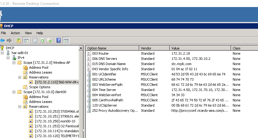
Below article point us to root caused with AP discovery. DNS was added 2 days after HQ when they made their WIFI controller alive 4/5 days ago. Hence lost of comms to AP from 2.17 (controller).
We planning to move to out own domain and use different domain controller.
DNS based controller discovery -
https://www.flomain.de/2014/07/how-to-controller-discovery/
This is a very handy method, when you can not change the VLAN, the AP will be placed into or you want to be very flexible where to connect your AP’s. The AP will get an IP address from a DHCP server and will start L2 controller discovery. As this will fail, the AP will try to get the controller IP via DNS.
When working with MSM controllers, the AP will try to resolve those names:
- cnsrv1.your-domain.com
- cnsrv2.your-domain.com
- cnsrv3.your-domain.com
- cnsrv4.your-domain.com
- cnsrv5.your-domain.com
It is not necessary, to resolve all the names. Just on for every controller and you are fine.
When you have a unified controller, the AP will try to resolve a different name, which is:
- HPN.your-domain.com
If you have more than one controller, you should resolve all IP addresses from that name. Doing it that way, with a round robbing algorithm at the DNS server, will lead to a good sharing of AP’s between those controllers.
Keep in mind, that all AP’s will come with a MSM image, even when you have a unified controller and even after a hard reset, the AP will boot up with a MSM boot code. This mean, you should always put both name formats into your DNS system.
C:\MSM>nslookup cnsrv1
Server: har-ad8-01.stc.ricplc.com
Address: 172.31.4.50
Name: cnsrv1.stc.ricplc.com
Address: 172.30.69.48
C:\MSM>nslookup cnsrv2
Server: har-ad8-01.stc.ricplc.com
Address: 172.31.4.50
*** har-ad8-01.stc.ricplc.com can't find cnsrv2: Non-existent domain
C:\MSM>nslookup hpn
Server: har-ad8-01.stc.ricplc.com
Address: 172.31.4.50
Name: hpn.stc.ricplc.com
Address: 172.30.69.48
- Mark as New
- Bookmark
- Subscribe
- Mute
- Subscribe to RSS Feed
- Permalink
- Report Inappropriate Content
01-04-2016 07:43 AM - edited 01-04-2016 07:43 AM
01-04-2016 07:43 AM - edited 01-04-2016 07:43 AM
Re: Implementation WIFI network using MSM 760
Hi John,
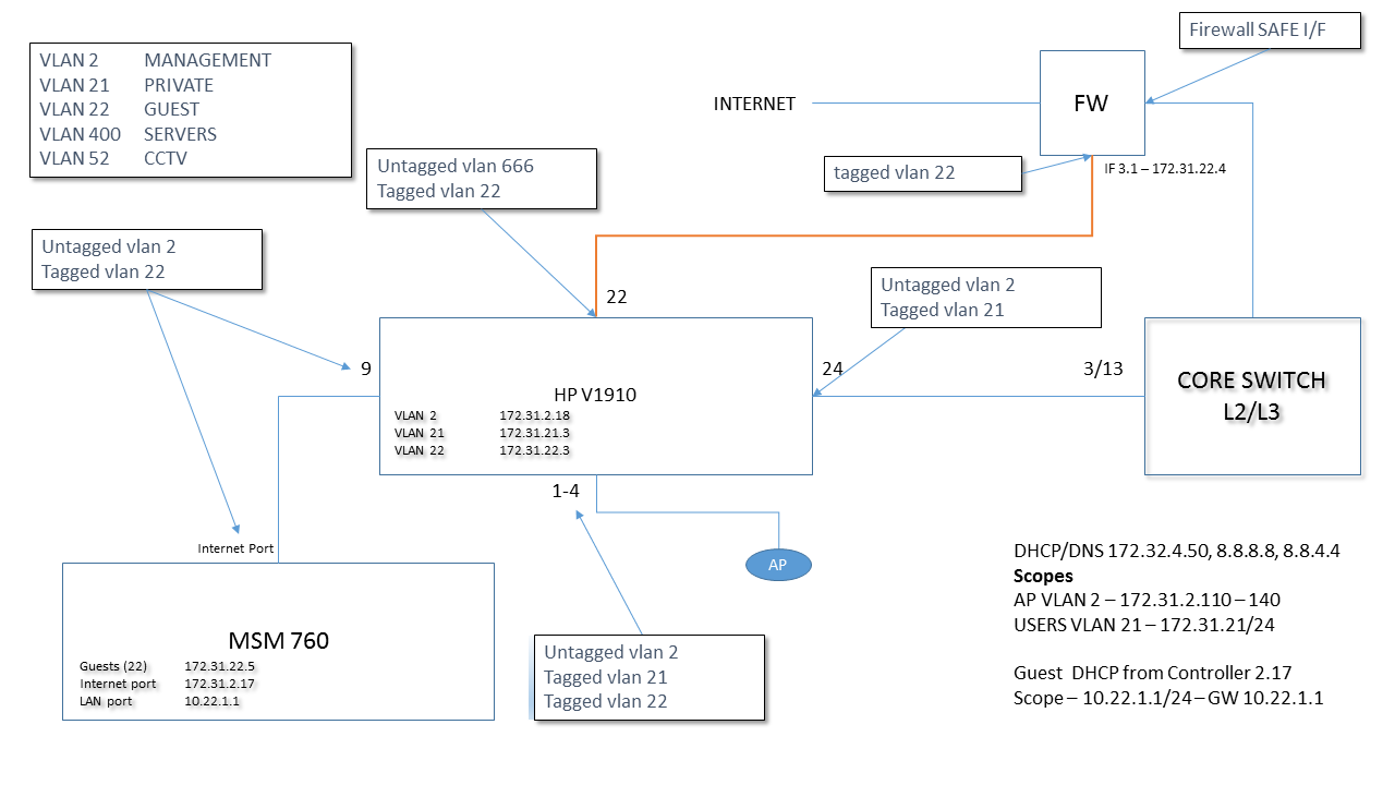
Happy new year, all working now - I need to add Active route to ensure that guest traffic is forward to FW I/F 172.31.22.4 1
Active routes	?
Interface	Destination	Mask	        Gateway	     Metric	Delete
LAN port	10.22.1.0	255.255.255.0	*	        0
Guests	        172.31.22.0	255.255.255.0	*	        0
Internet port	172.31.2.0	255.255.255.0	*	        0
LAN port	10.22.100.0	255.255.254.0	*	        0
Guests	        172.31.22.0	255.255.255.0	172.31.22.4	1
I have one questions – implementation as I have it – will route all guess traffic back to controller and leave controller via vlan 22 and to the FW. This is good, however – when expanding AP for remote offices – all guest traffic will be routed back to controller and back. In one office we have more than 60 users – although I don’t think traffic wouldn’t be large but if this traffic does get large - how can I change this so that guest traffic passes to out from AP to say new vlan 222 -> FW -> Internet – i.e. Decentralised – this option is offered when using automated workflow for employee vsc but not for guest.
Any advice appreciated. See below for final working network diagram.
Kind Regards,
Michael